Select Add Operation to select an operation.
![]()
Implement Profile settings are important for accurate performance of John Deere AMS applications, such as AutoTrac. Refer to Implement Profile Overview for additional theory of operation.
If a recognized implement control unit is connected, the current implement profile is saved and the new implement profile is loaded. Adding a second implement with a GreenStar Rate Controller (GRC) does not cause the current profile to save and close.
NOTE: After the profile is configured, use the Work Setup application to set up documentation.
When an implement is connected that is not recognized, a profile must be created for that implement. To complete setup, enter the following information:
Select Yield Documentation, Specialty Crop if the implement is using a yield documentation control unit.
Select Rate Controller if the implement is using a John Deere Rate Controller.
Operations from the rate controller are automatically set up in the virtual implement.
This setting defines the operation of the implement for mapping and documentation purposes. You may select more than one operation.
The following operations are available:
|
|
|
|
|
|
|
|
|
|
|
|
|
Select Add Operation to select an operation. |
|
|
Select Remove Operation to remove an operation. |
|
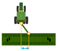
Width of the area worked (tilled, planted, sprayed, or harvested) on a single pass through the field. For example, on a chisel plow, measure the distance between each outside chisel, shovel, or sweep. Select either Meters (or Feet) or Rows and enter measurements.
The following applications require Working Width setting:
Mapping
Guidance
Instructions for Measuring Working Width
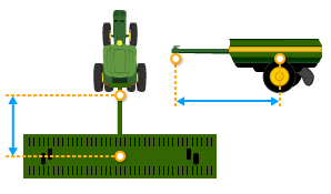
In-line distance from connection point to point where the operation occurs. For example, where seed or product is dropped, a crop is harvested, or ground is tilled.
The following applications require Work Point setting:
Mapping
Section Control
Work Setup
Instructions for Measuring Work Point
Recording source used for documentation and mapping. Select a recording source from the available work recording triggers.
The following applications require Work Recording setting:
Mapping
Work Setup
Connection type, or hitch, describes how implement is attached to machine and controls how display determines implement movement behind the machine.
NOTE: Connection offset measurements are entered in Machine Profile.
The following applications require Connection Type setting:
Mapping
Section Control
Work Setup
|
|
Drawbar |
|
Rear 3-Point |
|
|
Front 3-Point |
|
Wagon-Hitch |
|
|
Ball |
|
Clevis |
|
|
Hitch-Hook |
|
Piton |
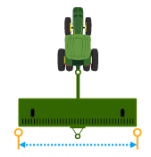
Lateral Offset
Lateral distance from center point of the machine to center point of the working width of implement.
The following applications require Lateral Offset setting:
Mapping
Guidance
Instructions for Measuring Lateral Offset
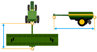
 Center of Rotation
In-line distance from connection point to the implement center of rotation while in working position. Usually, this is where load-bearing parts of the implement make contact with the ground.
Center of Rotation offset is important to accurately model trailing action of implement around curves.
The following applications require Center of Rotation setting:
Mapping
Section Control
Work Setup
Guidance
AutoTrac Turn Automation
NOTE: Measure center of rotation while the implement tool is engaged.
Instructions for Measuring Center of Rotation
 Rear Connection
In-line distance from the connection point to the rear connection point of the implement.
The following application requires Rear Connection setting:
Mapping
 Overall Width
Lateral distance from one side of the implement to the other side at the widest point of the implement.
The following application requires Overall Width setting:
Autonomy
Overall Length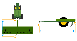
In-line distance from the connection point to the rear-most point of the implement.
The following application requires Overall Length setting:
Autonomy
|
Select Delete Profile button to delete current implement profile settings. |
|
Add an implement receiver or edit receiver offsets.
|
Select Add Receiver Mount button to add an implement receiver. |
|
Select receiver offsets to edit implement receiver offsets.


