Normally, this offset is set to 0.
Some implements may pull to one side. Lateral Offset can be used to compensate for the draft.
NOTE: When using multiple implements, only the lateral offset for the first implement is used.
To avoid errors in mapping, documentation, and section control, combine the lateral offsets from all implements and enter that value for the first implement. For example, if the first implement is 5.1 cm (2 in) to the right and the second implement is 2.5 cm (1 in) to the left, enter 1.3 cm (0.5 in) to the right.
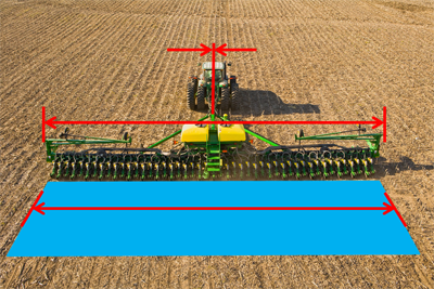
With implement engaged in ground, use AutoTrac to drive three passes.
Measure widths of the two rows on either side of middle pass.
Set offset direction to the side of implement that has the wider row.
Find the difference between each measurement and correct row spacing. If machine is tracking correctly and Working Width is accurate, the two numbers will be the same.
Divide number by two and enter this for Lateral Offset.
For example, if the two rows measure 86 cm (34 in.) and 66 cm (26 in.), and correct row spacing is 76 cm (30 in.), divide 10 cm (4 in.) by 2. Enter 5 cm (2 in.) as lateral offset.