Quick Links
Quick Links
Quick Links
Implement Profile settings are important for the accurate performance of John Deere AMS applications, such as mapping and Section Control. The implement controller sets most of the Implement Profile settings automatically. Once all the profile settings are input and saved, all the settings load each time the implement is connected.
Profile Name— is set automatically based on the implement that is auto-detected. View the type of machine, the model number, the serial number, and when the profile was last modified.

Profile Name
|
Scroll Up— allows you to scroll up through the list. |
Scroll Up |
|
Scroll Down— allows you to scroll down through the list. |
Scroll Down |
|
Save— saves all inputs. |
Save |
|
Cancel— ignores all inputs. |
Cancel |
|
Reset Profile— returns all the inputs that you set to the factory defaults originally stored on the implement controller. |
Reset Profile |
Connection Type— is the style of hitch that connects the implement to the tractor. The connection type also determines how the tractor and implement appear to move on the screen.
Connection Type
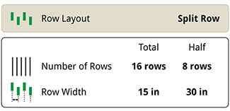
Working Width— is the overall width of the implement and the style of row unit configuration on the implement.
Working Width
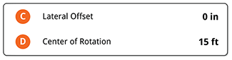
Dimensions— establishes the center of implement rotation and hitch offset.
Dimensions
Work Point— is the distance from the hitch connection to the point of seed delivery.

Work Point
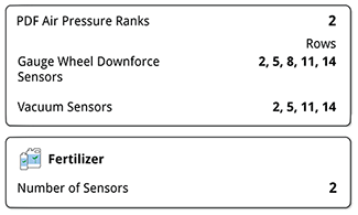
Sensor Setup— is the quantity and location of various sensors on the implement.
Sensor Setup
Mechanical Delay— is the travel time of the seed from the point of seed release (from the row unit) to the soil.

Mechanical Delay
Section Control— select if a GPS signal is marginal. When enabled, the outer row unit sections are grouped together to avoid unintentional shutoffs as the GPS signal drifts.

Section Control
Modify the Work Point when switching between wide and narrow row spacing if your implement is a split-row configuration.
IMPORTANT: Perform this procedure at the beginning of the season or whenever the machine or implement configuration has changed. Verifying the accuracy of the values ensures proper implement function and can resolve issues with other features such as section control. Once the dimensions are measured and entered, section control can be set and fine-tuned.
|
Menu |
|
Applications |
|
Equipment Manager |
Measure, enter, and verify that all tractor dimensions are correct within the machine profile. These dimensions include GPS offsets, connection type, and connection offsets. For more information on how to change these values and take these measurements, see Equipment Manager.
Select the Implement Profile input box.
Implement Profile
Select the Profile Name input box to edit (personalize) the name using the keypad.
NOTE: Changing the name is not a requirement.
Profile Name
IMPORTANT: Before measuring dimensions, enter the field and drive in a straight line for a short distance with the implement lowered as if planting.
For more information on each setting and measurement procedures (when applicable), select the corresponding hyperlink.
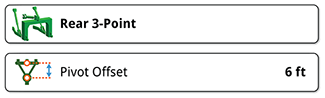
Select Connection Type. Select between drawbar or 3-point hitch.
Connection Type
If 3-point hitch is chosen, you will be prompted to define if the connection is non-pivoting or pivoting. Non-pivoting is typically used with a fully integral implement or with some integral implements equipped with lift-assist wheels. Pivoting is typically used with a semi-integral drawn implement.
If pivoting is chosen, you will be prompted to enter the Pivot Offset.
Select Working Width. Change the number of rows and row width as needed.
Working Width
Select Dimensions. Change the lateral offset and center of rotation values as needed.
Dimensions
Enter the Lateral Offset. If the implement has no offset, select Center. No offset value is needed if Center is selected. If the implement has a left or right offset, select the appropriate offset and enter the offset value. To measure the offset value, follow the procedure on the Lateral Offset page.
Measure and enter the Center of Rotation. Measure from the drawbar pin or the implement pivot pin to the implement main frame wheel axle.
Select Work Point. Measure and enter the distance from the drawbar pin or implement pivot pin to the point where seed is dropped.
Work Point
Select Sensor Setup. Change the number of vacuum sensors as needed.
Sensor Setup
Select Mechanical Delay. Change the values as needed.
Mechanical Delay
Turn section control Group Outer Rows on or off as needed. Select if a GPS signal is marginal. When enabled, the outer row unit sections are grouped together to avoid unintentional shutoffs as the GPS signal drifts.
Group Outer Rows
If needed, add or modify the implement receiver settings. For more information, see Equipment Manager.
After measuring and changing values as needed, determine how your inputs are processed by selecting one of the following:
|
Save |
|
Cancel |
|
Reset Profile |