When a planter is connected, some Implement Profile settings are automatically set by the implement control unit. Refer to Implement Profile Overview for additional theory of operation.
Connection type, or hitch, describes how implement is attached to machine and controls how display determines implement movement behind the machine.
NOTE: Connection offset measurements are entered in Machine Profile.
NOTE: Rear 2-point connection type offset from GreenStar 3 2630 Display is replaced by rear 3-point offset and a pivot offset.
The following applications require Connection Type setting:
Mapping
Section Control
Work Setup
|
|
Drawbar |
|
Rear 3-Point |
|
|
Front 3-Point |
|
Wagon-Hitch |
|
|
Ball |
|
Clevis |
|
|
Hitch-Hook |
|
Piton |
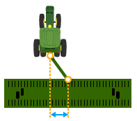
Some implements have a pivoting hitch that connects to the machine's rear 3-point hitch. The offset for this pivoting location is required for the display to determine implement movement behind the machine.
NOTE: Pivot offset setting is available when rear 3-point is selected as the connection type.
Instructions for Measuring Pivot Offset
Width of the area worked on a single pass through the field. Select Row Layout (Single or Split Row), then select either Meters (or Feet) or Rows and enter measurements.
The following applications require Working Width setting:
Mapping
Guidance
|
Single Row - Use this configuration when the planter is only a single row design. |
|
|
Split Row - If the planter is a split row design, select this option. Split row must always remain selected for planters of this design. |
|
Instructions for Measuring Working Width
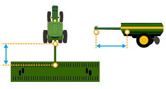 Front Length
In-line distance from the front connection point to the first working point of the implement.
The following application requires Front Length setting:
Mapping
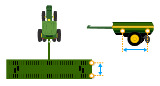 Working Length
In-line distance from the first working point to the second working point.
The following application requires Working Length setting:
Mapping
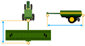
 Lateral Offset
Lateral distance from center point of the machine to center point of the working width of implement.
The following applications require Lateral Offset setting:
Mapping
Guidance
Instructions for Measuring Lateral Offset
 Center of Rotation
In-line distance from connection point to implement’s center of rotation while in working position. Usually this is where load bearing parts of the implement make contact with the ground.
Center of Rotation offset is important to accurately model trailing action of implement around curves.
NOTE: This offset is NOT needed if Connection Type is set to Front 3-point or Non-Pivoting Rear 3-point.
The following applications require Center of Rotation setting:
Mapping
Section Control
Work Setup
Guidance
AutoTrac Turn Automation
NOTE: Measure center of rotation while the implement tool is engaged.
Instructions for Measuring Center of Rotation
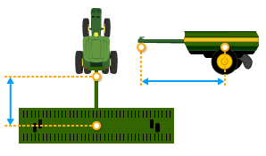
 Rear Connection
In-line distance from the connection point to the implement's rear connection point.
The following application requires Rear Connection setting:
Mapping
In-line distance from connection point to point where seed is dropped.
The following applications require Work Point setting:
Mapping
Section Control
Work Setup
Instructions for Measuring Work Point
|
Controller Settings - Select to modify the GreenStar Rate Controller settings. |
|
|
Working Width - Width of the area worked on a single pass through the field. Working width is automatically populated by the planter working width. |
|
Add an implement receiver or edit receiver offsets.
|
Select Add Receiver Mount button to add an implement receiver. |
|
Select receiver offsets to edit implement receiver offsets.


