When a baler is connected, some Implement Profile settings are automatically set by the implement control unit. Refer to Implement Profile Overview for additional theory of operation.
Connection type, or hitch, describes how implement is attached to machine and controls how display determines implement movement behind the machine.
NOTE: Connection offset measurements are entered in Machine Profile.
The following applications require Connection Type setting:
Mapping
Overlap Control
Work Setup
|
|
Drawbar |
|
Wagon-Hitch |
|
|
Ball |
|
Clevis |
Width of the area worked on a single pass through the field. This is the full cutting width that was merged to create the windrow that is being baled.
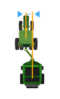
Instructions for Measuring Working Width
Lateral Offset
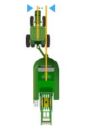 Lateral distance from the center point of the machine to the center point of the working width of the implement.
The following applications require Lateral Offset setting:
Mapping
Guidance
Instructions for Measuring Lateral Offset
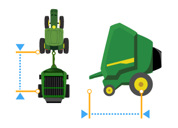
Center of Rotation
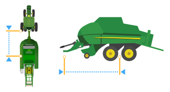 In-line distance from the connection point to the implement center of rotation while in working position. Usually, this is where load-bearing parts of the implement make contact with the ground.
Center of Rotation offset is important to accurately model the trailing action of the implement around curves.
The following applications require Center of Rotation setting:
Mapping
Overlap Control
Work Setup
Guidance
AutoTrac Turn Automation
NOTE: Measure the center of rotation while the implement tool is engaged.
Instructions for Measuring Center of Rotation
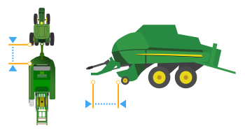 In-line distance from the connection point to where the crop is picked up.
The following applications require Work Point setting:
Mapping
Work Setup
Instructions for Measuring Work Point
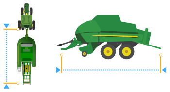 In-line distance from the connection point to where the bale is dropped.
The following applications require Bale Drop Point setting:
Mapping
Work Setup
Lateral Offset
 Lateral distance from the center point of the machine to the center point of the working width of the implement.
The following applications require Lateral Offset setting:
Mapping
Guidance
Instructions for Measuring Lateral Offset
Center of Rotation
 In-line distance from the connection point to the implement center of rotation while in working position. Usually, this is where load-bearing parts of the implement make contact with the ground.
Center of Rotation offset is important to accurately model the trailing action of the implement around curves.
The following applications require Center of Rotation setting:
Mapping
Overlap Control
Work Setup
Guidance
AutoTrac Turn Automation
NOTE: Measure the center of rotation while the implement tool is engaged.
Instructions for Measuring Center of Rotation
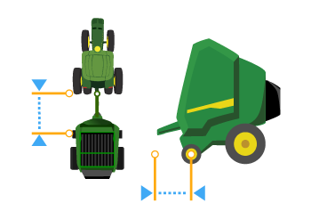 In-line distance from the connection point to where the crop is picked up.
The following applications require Work Point setting:
Mapping
Work Setup
Instructions for Measuring Work Point
 In-line distance from connection point to where the bale is dropped.
The following applications require Bale Drop Point setting:
Mapping
Work Setup
Add an implement receiver or edit receiver offsets.
|
Select Add Receiver Mount button to add an implement receiver. |
|
Select receiver offsets to edit implement receiver offsets.
|
Select Add Steamer button to add steamer dimensions. |
|


