
Drawbar

Wagon-Hitch

Ball

Clevis

Hitch-Hook

Piton

Rear 3-Point
NOTE: Set up ISOBUS control unit in ISOBUS VT prior to configuring Implement Profile settings.
When an ISOBUS control unit is connected, some Implement Profile settings are automatically set by the control unit. Refer to Implement Profile Overview for additional theory of operation.
To complete setup, enter the following information:
Connection type, or hitch, describes how implement is attached to machine and controls how display determines implement movement behind the machine.
NOTE: Connection offset measurements are entered in Machine Profile.
The following applications require Connection Type setting:
Mapping
Work Setup
|
|
Drawbar |
|
Wagon-Hitch |
|
|
Ball |
|
Clevis |
|
|
Hitch-Hook |
|
Piton |
|
|
Rear 3-Point |
|
|
Some implements have a pivoting hitch that connects to the machine's rear 3-point hitch. The offset for this pivoting location is required for the display to determine the implement movement behind the machine.
NOTE: Pivot Offset setting is available when rear 3-point is selected as the Connection Type.
Instructions for Measuring Pivot Offset
Working Width is the width of a single pass.
The following applications require Working Width setting:
Mapping
Work Setup
Guidance
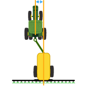
Instructions for Measuring Working Width
 In-line distance from the connection point to the implement’s Center of Rotation while in working position. Usually, this is where the load-bearing parts of the implement make contact with the ground.
The Center of Rotation offset is important to accurately model the trailing action of the implement around curves.
NOTE: This offset is NOT needed if Connection Type is set to Front 3-point or Non-pivoting Rear 3-point.
NOTE: When using an AEF-certified control unit with the Product Applicator machine profile, set the Center of Rotation to 0.
The following applications require Center of Rotation setting:
Mapping
Work Setup
Guidance
AutoTrac Turn Automation
NOTE: Measure center of rotation while the implement tool is engaged.
Instructions for Measuring Center of Rotation
 Lateral distance from the center point of the machine to the center point of the working width of the implement.
NOTE: When using an AEF-certified control unit with the Product Applicator machine profile, set the Lateral Offset to 0.
The following applications require the Lateral Offset setting:
Mapping
Guidance
Instructions for Measuring Lateral Offset
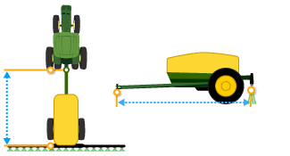 In-line distance from the connection point to the point where product is dropped.
NOTE: When using an AEF-certified control unit with the Product Applicator machine profile, set the Work Point only on the machine profile and not the implement profile.
The following applications require Work Point setting:
Mapping
Work Setup
Instructions for Measuring Work Point
Use work recording to select the desired recording source.
Add an implement receiver or edit receiver offsets.
|
Select Add Receiver Mount button to add an implement receiver. |
|
Select receiver offsets to edit implement receiver offsets.
|
Select Reset Profile button to delete the current implement profile settings. |
|
If an implement is connected, settings stored on the implement control unit are loaded to the display.
NOTE: If implement profile fails to load properly, select the Reset Profile button to reload settings.
