Drawbar

Rear 3-Point

Front 3-Point

Wagon-Hitch

Ball

Clevis

Hitch-Hook

Piton
NOTE: Set up air seeder in ISOBUS VT prior to configuring Implement Profile settings.
When an air seeder is connected, some Implement Profile settings are automatically set by the implement controller. Refer to Implement Profile Overview for additional theory of operation.
Connection type, or hitch, describes how implement is attached to machine and controls how display determines implement movement behind the machine.
NOTE: Connection offset measurements are entered in Machine Profile.
The following applications require Connection Type setting:
Mapping
Section Control
Work Setup
|
|
Drawbar |
|
Rear 3-Point |
|
|
Front 3-Point |
|
Wagon-Hitch |
|
|
Ball |
|
Clevis |
|
|
Hitch-Hook |
|
Piton |
Some implements have a pivoting hitch that connects to the machine's rear 3-point hitch. The offset for this pivoting location is required for the display to determine implement movement behind the machine.
NOTE: Pivot offset setting is available when rear 3-point is selected as the connection type.
Instructions for Measuring Pivot Offset
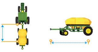 Center of Rotation
In-line distance from connection point to implement’s center of rotation while in working position. Usually this is where load bearing parts of implement make contact with ground.
Center of Rotation offset is important to accurately model trailing action of implement around curves.
NOTE: This offset is NOT needed if Connection Type is set to Front 3-point or Non-pivoting Rear 3-point.
The following applications require Center of Rotation setting:
Mapping
Section Control
Work Setup
Guidance
AutoTrac Turn Automation
NOTE: Measure center of rotation while the implement tool is engaged.
Instructions for Measuring Center of Rotation
 Lateral Offset
Lateral distance from center point of machine to center point of the working width of implement.
The following applications require Lateral Offset setting:
Mapping
Guidance
Instructions for Measuring Lateral Offset
|
Select Tank Configuration to set the method that the tanks are emptied of product. |
|
NOTE: When using alternate or merge tank configuration, Section Control performance tuning is unavailable.
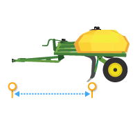 Work Point
Work Point is the distance from connection point to the location where product is applied. Set a work point measurement for each tank on multi-tank air carts.
NOTE: When using alternating or merged tanks, work point cannot be modified. Set tank configuration to individual to make changes to work point.
The following applications require Work Point setting:
Mapping
Section Control
Work Setup
Instructions for Measuring Work Point
Mechanical delay is the average time for the product to reach the ground after an ON or OFF command. It may need to change with each machine, implement, and display combination. Set a mechanical delay for each tank on multi-tank air carts.
NOTE: When using alternating or merged tanks, mechanical delay is set to the shortest off time and longest on time values.
The following applications require Mechanical Delay settings:
Mapping
Section Control
Work Setup
Instructions for Measuring Mechanical Delay
|
Select Reset Profile button to delete current implement profile settings. |
|
If an implement is connected, settings stored on the implement controller are loaded to the display.
NOTE: If implement profile fails to load properly, select Reset Profile button to reload settings.
Add an implement receiver or edit receiver offsets.
|
Select Add Receiver Mount button to add an implement receiver. |
|
Select receiver offsets to edit implement receiver offsets.