Refer to Implement Profile Overview for additional theory of operation.
NOTE: Set up tillage implement in ISOBUS VT before configuring Implement Profile settings.
Connection type, or hitch, describes how implement is attached to machine and controls how display determines implement movement behind the machine.
NOTE: Connection offset measurements are entered in Machine Profile.
The following applications require Connection Type setting:
Mapping
Section Control
Work Setup
|
|
Drawbar |
|
Rear 3-Point |
|
|
Front 3-Point |
|
Wagon-Hitch |
|
|
Ball |
|
Clevis |
|
|
Hitch-Hook |
|
Piton |
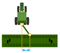 Lateral Offset
Lateral distance from center point of the machine to the center point of the working width of implement.
The following applications require Lateral Offset setting:
Mapping
Guidance
Instructions for Measuring Lateral Offset
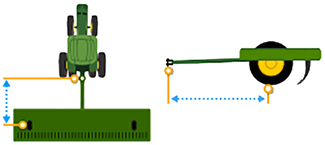
In-line distance from connection (or pivot) point to the implement’s center of rotation while in working position. Usually this is where load bearing parts of implement make contact with the ground.
Center of Rotation offset is important to accurately model trailing action of implement around curves.
NOTE: This offset is NOT needed if Connection Type is set to Front 3-point or Non-Pivoting Rear 3-point.
The following applications require Center of Rotation setting:
Mapping
Section Control
Work Setup
Guidance
AutoTrac Turn Automation
NOTE: Measure center of rotation while the implement tool is engaged.
Instructions for Measuring Center of Rotation
NOTE: These dimensions are only visible when using certain implements.
Dimensions are provided by the implement and cannot be edited. The following measurements are populated by the implement:
Lateral Offset
Center of Rotation
In-Line Offset
Width
Length
In-Ground Turn Radius
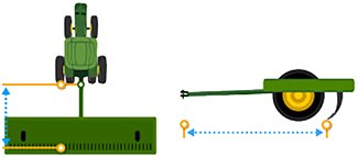
In-line distance from connection point to the location where product or work is applied. For example, where the ground is tilled.
The following applications require Work Point setting:
Mapping
Section Control
Work Setup
Instructions for Measuring Work Point
Mechanical delay is the average time for the tool to reach the ground after an ON or OFF command. It may need to change with each machine, implement, and display combination.
The following applications require Mechanical Delay settings:
Mapping
Section Control
Work Setup
Instructions for Measuring Mechanical Delay
Add an implement receiver or edit receiver offsets.
|
Select Add Receiver Mount button to add an implement receiver. |
|
Select receiver offsets to edit implement receiver offsets.


